|
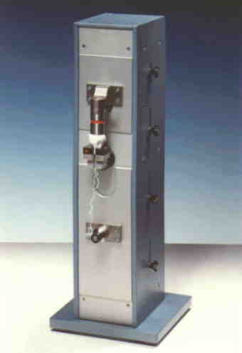
The mechanical part of the test equipment consists essentially of two motors and of the force transducer. This transducer generates an electrical output signal proportional to the pressure or tensile strength acting on it. A fitting part attached to the force transducer which is arranged in the center of the front panel can be replaced in conformity with the plug size. A counterpart is provided on the pressure part which can be replaced as well depending on the varying sizes.
Each one motor is intended for the introduction of the pressure and tensile force, resp. The force generated by the motor is translated via the appropiate gears and ballscrews into the required vertical motion. The four limit switches LS1 - LS4 on the right side are provided for the protection of the force transducer and of the mechanics as well as for the distance optimization in the event of plugs varying size. These limit switches can be loosened and vertically adjusted by one half rotation of the star knob. |